
Project 309.AUS covered an as-built BIM model of a commercial and office building in Australia. The work ran from November 2021 to January 2022 and produced a Revit model of the architecture and structure at LOD 300.
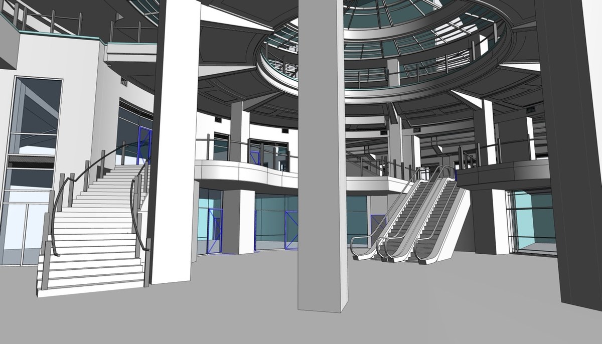
Project snapshot
The building covers about 7,400 m² (79,650 sq ft) across eight levels. Four of those levels sit below ground. The client asked for a model that records real geometry, dimensions and levels, so the file could support later maintenance, renovation and design work. Inputs were a point cloud and site images. The deliverable was a Revit file, built with Revit, Navisworks and internal tools.
Why this building was demanding
Two features set the difficulty. Above ground, a curved facade carries curved windows. Below ground, four basement levels hold a dense frame of columns, beams and walls, with split-level floors between them. Neither feature shows clearly on a clean drawing set, so the model had to follow the scan rather than assumptions.
What the team aimed for
- A 3D architecture and structure model that stays within ±15 mm (±0.6 in) of the point cloud.
- Curved walls and windows that read as smooth, continuous elements.
- Structural junctions that keep vertical elements aligned from floor to floor.
Where it got tricky
Curved point cloud data is hard to turn into a clean surface, and the windows could not use standard families because each one had to match the curve and lean of its wall. In the basements, stepped slabs needed separate height checks, and dense junctions made the real connections hard to read. The wide car-park footprint also made it harder to match floor points across a large area.
How the team handled it
For the facade, the team fitted reference circles to thin horizontal slices of the cloud and averaged them into one arc. Custom windows with adjustable radius and rotation then sat flush against it. For split levels, sections verified each height before slabs were modeled as reference masses. For junctions, 3D section views and site photos isolated each connection so the real overlaps could be reproduced.
What the owner gets
Design teams receive existing-condition data that is ready to use, so they can begin sooner and with fewer interruptions from missing measurements. The facility team gets a record of where columns, beams, walls and curved windows actually sit.
Owners with similar buildings can review the approach in more detail through the full project page for this Australian office building.
Reference: https://vibimglobal.com/projects/revit-modeling-for-an-office-building-in-australia/
See more:
- https://vibim.wordpress.com/2026/10/23/revit-modeling-for-an-office-building-in-australia/
- https://vibim-syndication.pages.dev/revit-modeling-for-an-office-building-in-australia/
ViBIM
10th floor, CIT Building, No 6, Valley 15, Duy Tan street, Cau Giay ward, Hanoi, Vietnam
(+84) 944.798.298
https://vibimglobal.com/