
Retrofit work starts with a question: what is actually in the building? For a large office in the western United Kingdom, the answer came from point cloud and TrueView data, turned into Revit models by a team of twelve between October and December 2024.
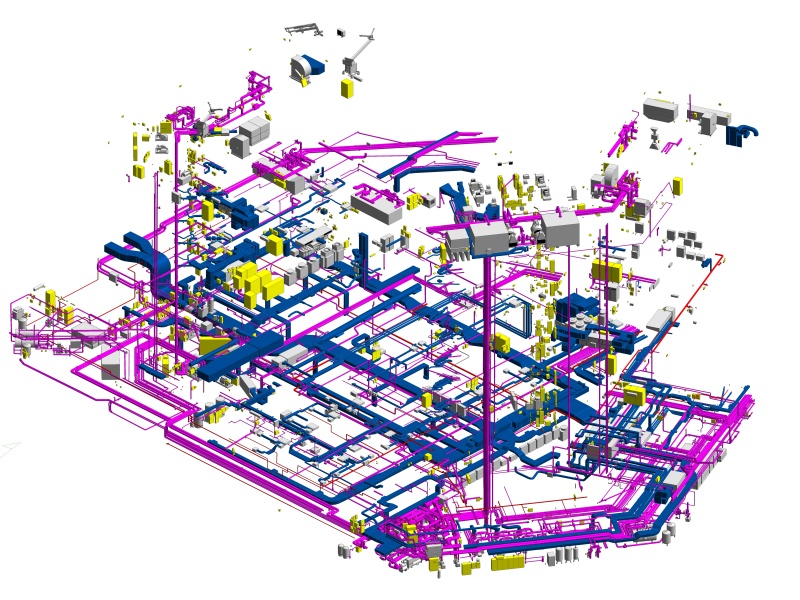
The building at a glance
The office has two basement levels and fourteen upper floors, with a total area of 4,600 m². The client remains confidential. The scope covered the whole interior and exterior of the main building, its MEP systems, the facades of neighboring buildings and the surrounding topography, all developed to LOD300.
Why it was demanding
Size forced the model into three files for architecture, structure and MEP, so alignment between them needed active management. MEP estimating began with little more than PDFs and exterior photographs. Basement scans were weak, and rooftop plant rooms connected to long service shafts that were difficult to capture. With a similar project for the same client running at the same time, scheduling was tight.
What kept it on track
- A unified coordinate system and clear ownership of objects in each file.
- A federated model for coordination, with regular clash checks in Revit and Navisworks.
- A material check using filters, schedules and TrueView.
- Benchmarking against comparable projects to estimate MEP time and resources.
- Parametric families, dedicated shaft modeling and several QA-QC layers, including point cloud analysis tools.
Why it matters for owners
Better estimates help stakeholders plan duration and cost. Tighter models reduce clashes before construction. Detailed data also supports operation, maintenance and later upgrades across the building's life.
A note on MEP accuracy
The MEP model targeted a tolerance within ±15 mm and followed the physical configuration of equipment, ductwork, piping and cable trays as documented in shop drawings or manufacturer technical documents. Experienced staff supervised junior modelers, and internal tools helped the team inspect large volumes of objects within a limited QA-QC window. Dense zones such as basements, rooftops and service shafts combined with low scan quality made full precision difficult, so those areas received the most review attention.
Readers who want to see how this kind of work is planned from the first scan can explore the full project record on the source page below, where the specification table lists inputs, deliverables and software.
Reference: https://vibimglobal.com/projects/revit-modeling-services-for-office-building-at-uk/
See more:
- https://vibim.wordpress.com/2026/10/29/revit-modeling-services-for-office-building-at-uk/
- https://vibim-syndication.pages.dev/revit-modeling-services-for-office-building-at-uk/
ViBIM
10th floor, CIT Building, No 6, Valley 15, Duy Tan street, Cau Giay ward, Hanoi, Vietnam
(+84) 944.798.298
https://vibimglobal.com/